Blade Angle Measurement on Wind Turbines – Comparison of Methods
Different measurement methods are available for determining blade angles and geometric deviations on wind turbines. These range from template-based measurements and photogrammetry to drones and 3D total stations, as well as dynamic laser measurement for comparing blade behaviour.
The methods differ not only in the type of measurement. The key question is which condition of the wind turbine is being measured.
A static measurement describes the geometry of the rotor in a defined standstill position. A dynamic measurement, by contrast, captures the rotor under the real aerodynamic and structural conditions of operation.
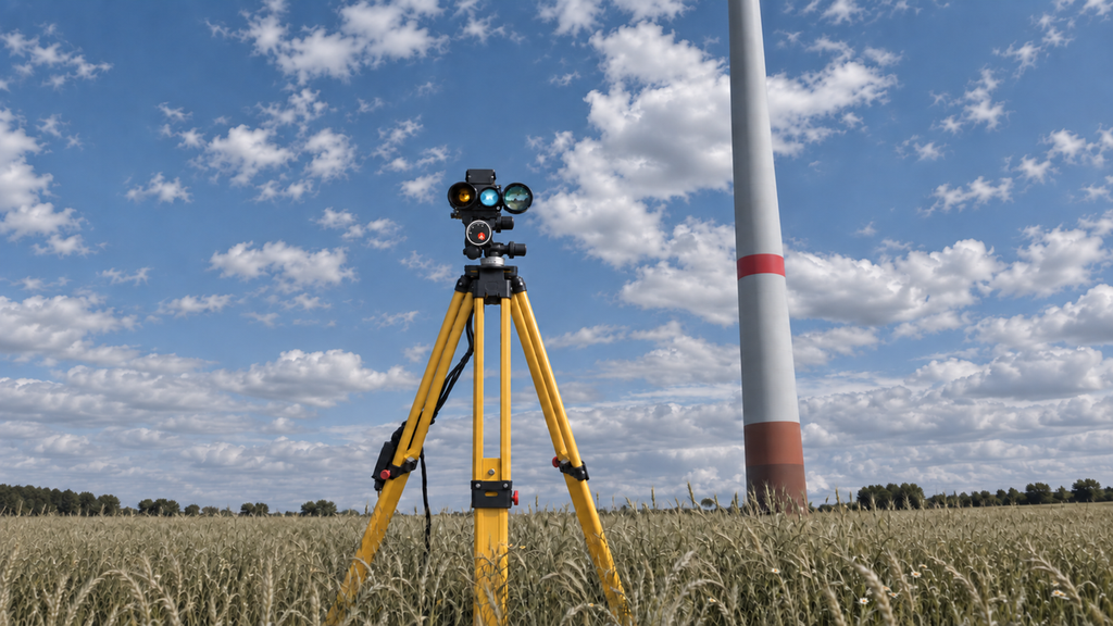
Static and dynamic measurements answer different questions
With a static measurement, the wind turbine is stopped and the rotor blade is measured in a defined position. This primarily allows geometric quantities and control-relevant boundary conditions to be determined.
During operation, however, blade loads, deflection, pitch angle and structural response change continuously. The rotor blades are therefore not only in a static geometric condition, but operate under real loads.
A dynamic measurement therefore answers an additional question:
How does the rotor actually behave during operation?
Particularly when assessing blade angle deviations and their effect on the turbine, this information can be decisive.
Template-based blade angle measurement
A traditional approach is measurement using a geometric template. The template is aligned with the blade geometry using target points and can determine a defined position of the stationary rotor blade visually and mechanically.
The method requires direct access to the rotor blade and the turbine to be shut down. A particular challenge is the reproducible positioning of the template.
Rotor blades have manufacturing-related geometric tolerances. As a result, the intended position of the template on the rotor blade may differ geometrically. For a reliable comparison, it must therefore be ensured that the blade is actually measured at a defined and reproducible position.
In addition, only the static condition is measured. Statements about blade deflection, rotor behaviour or structural responses during operation are not possible with template measurement alone.
Photogrammetry
Photogrammetric methods determine geometric quantities from image data. Positions, distances and geometric relationships can be derived from suitable images.
For static measurement tasks, this can provide precise information. However, the turbine or at least the rotor blade must generally be positioned and then evaluated from defined positions.
If the aim is to investigate how a blade angle deviation affects the three rotor blades during real operating conditions, additional or dynamic measurement approaches are required.
Drone-based measurement
Drones make it possible to capture visually difficult-to-access areas of a wind turbine. They are used particularly for visual inspections and can also support geometric measurement tasks.
Their advantage lies in flexible positioning and in the ability to capture large areas of the turbine optically.
For reproducible measurements of a rapidly rotating rotor during normal turbine operation, however, tower-movement, positioning and temporal referencing present particular challenges.
Drone-based measurement and dynamic rotor measurement therefore fulfil different tasks.
3D total station
3D total stations enable precise geometric measurement of defined points and are particularly suitable for static reference and geometry measurements.
This allows positions and geometric relationships to be determined on a stationary wind turbine.
For continuous measurement of rapidly moving rotor blades during normal turbine operation, this measurement principle is less suitable because it is designed primarily for individual geometric measurement points.
Here too, the static measurement of a defined turbine condition is the primary focus.
Dynamic laser measurement
In dynamic laser measurement, the rotor blades pass one after another through a spatially fixed measurement line.
The distance profile is measured with high temporal resolution. This allows individual blade passages to be compared with each other while the turbine operates under normal conditions.
The main advantage over contactless distance measurement alone is that the actual operating condition of the rotor is captured.
The rotor blades are measured under the real aerodynamic loads. This makes it possible to compare relative blade angle deviations with information about rotor and turbine behaviour.
More than just measuring blade angles
Relative blade angle differences between the rotor blades can be determined from the individual blade passages.
At the same time, blade position and blade deflection can be measured relative to a fixed reference such as the tower axis. If this measurement is related to tower or nacelle movement, differences in blade angle and deflection become visible.
In addition, tower movements or nacelle movements can be observed.
This allows several measurement parameters to be related to each other under the same operating conditions:
Blade angle → blade movement → structural response → technical assessment
The measurement therefore describes not only geometric differences between the rotor blades, but also their behaviour under real operating conditions.
Which blade angle measurement method is the right one?
The methods fulfil different tasks. A static measurement is not fundamentally better or worse than a dynamic measurement.
The measurement task is decisive.
| Method | Typical focus | Turbine shutdown | Rotor in operation | Structural response |
|---|---|---|---|---|
| Template measurement | Static blade angle at a defined blade position | yes | no | no |
| Photogrammetry | Geometric and optical measurement | yes | no | additional measurement |
| Drone | Inspection and geometric measurement | depends on method | yes | additional measurement |
| 3D total station | Precise static geometry and reference measurement | yes | no | additional measurement |
| Dynamic laser measurement | Rotor behaviour under operating conditions | no | yes | can be captured in parallel |
For assembly, adjustment or verification of a defined geometric reference, a static measurement may be the appropriate solution.
If the aim is instead to investigate how uniformly the three rotor blades operate during ongoing operation, dynamic measurement provides additional information.
From geometric condition to operating behaviour
The development of measurement methods is therefore moving from purely static methods with direct access to the rotor blade towards contactless dynamic measurement of the operating rotor.
A static measurement answers primarily:
How is the rotor geometrically set in this defined condition?
A dynamic rotor measurement extends this question:
How do the rotor blades behave under real operating conditions – and is an existing deviation also reflected in the response of the turbine?
In simplified form:
Static measurement → geometric condition
Dynamic laser measurement → blade angle differences + behaviour under operating load
Particularly when assessing relative blade angle deviations, this distinction is relevant. Modern wind turbines continuously change their pitch angle. For a rotor that is as synchronised as possible, it is therefore particularly important whether the three rotor blades operate uniformly under comparable conditions.
Dynamic rotor measurement with Rotor LDM
Rotor LDM measures the rotor blades during operation using a spatially fixed laser measurement line.
Relative blade angle deviations are determined from the recurring blade passages. At the same time, blade position and deflection relative to the tower axis as well as the responses of the tower or nacelle can be considered.
The focus is therefore not only on geometric measurement, but on capturing and technically assessing actual rotor and turbine behaviour during operation.